Repressive Switches
Introduction
Our repressive designs are based upon the cooperative sensors by Plaxco et al. that have multiple split binding sites separated by a long, disordered loop. The binding of the first molecule is unfavourable as it requires both sides of the binding site to be brought together. Subsequent binding events are easier as the two sides of the binding are already closer. The longer and more disordered the loop the more cooperative the switch should be.
Our designs also bear resemblance to the staples of DNA origami in that the triggers act as staples that bring the DNA from a completely disordered chain into a structured loop.
One limitation of Nupack is that it is unable to generate pseudoknot structures involving more than one strand. Pseudoknots are RNA structures that contain two, parallel double-stranded hairpins separated by two single stranded loops such that base pairing occurs in a non-sequential manner i.e. if the strands involved are laid out in a flat circle their is no way to connect base-paired nucleotides without interactions crossing over each other. This makes them harder for computers to understand.
As our repressive strands are pseudoknot structures we had to design them by separating the trigger into two halves.
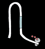
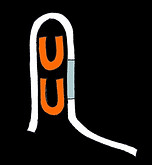
These switches have two different domain sequences a and b. Two sequential copies of domain a are separated from two sequential copies of b by a disordered loop. The rbs sequence is shared between the two b domains:
b b
GGAGACATAGA GGAGACATAGA
RBS
The trigger a*b* should close the structure in a cooperative fashion to hide the rbs. Three designs were made with loop sizes of 6, 20 and 50 nts. As loop length increases so should the Hill coefficient.
Each domain is of length 11nt as this is the helix repeat of RNA.
Due to budget constraints only the aabb20 design was tested in vitro. As well as testing a*b* we also tested a trigger that had all four domains i.e. a*a*b*b*.
aabb Switches
Loop of 6nt
Loop of 50nt
Loop of 20nt
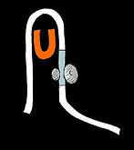
We designed a similar switch with four different domains arranged a then c then the loop then d then b. The acdb20 switch was tested in vitro with the triggers a*b* , c*d* and the long trigger c*a*b*d* with should act non-cooperatively with 1:1 stociometry.
acdb20 Switch
AB switches
Another set of switches were designed to test another aspect of cooperativity: increasing the number of binding sites. These switches also have split binding sites for triggers composed of two domains (called A and B to differentiate them from a and b).
Switch AB has two of one of each of these domains separated by a 50nt loop. Switch AABB has two A domains, a 50nt loop then two B domains. Switch AAABBB has three A domains, a 50nt loop then three B domains.
The rbs of this switch is located in the loop just before the first B domain of each switch. This means that the initiator methionine falls within the B domain. As each switch has a different number of B domains and each domain is 11nts long each switch therefore produces a translated, N-terminal peptide linker of a different sequence ahead of the downstream gene. We aimed to keep these linkers reasonably hydrophilic by changing the sequence of B within the structural constrains imposed by the designs. The initiator methionine of our fluorescent protein (mKate2) was removed.
The N-terminal linkers produced are:
AB: Met Ser
AABB: Met Gly Ser Gly Trp Gly
AAABBB: Met Ser Gly Ser Cys Pro Ala His Val


a
a
a
a
a
a
b
b
b
b
b
b
A
A
A
A
A
A
B
B
B
B
B
B
rbs hidden here
rbs hidden here
rbs hidden here
rbs in loop here
rbs in loop here
rbs in loop here
Initiator AUG
Initiator AUG
Initiator AUG
a*b* Trigger
a*b* Trigger

Loop of 20nt
a
b
c
d
rbs hidden here
c*d* Trigger
a*b* Trigger

Loop of 20nt
a
b
c
d
c*a*b*d* Trigger
A*B* Trigger
A*B* Trigger
A*B* Trigger
AB
AABB
AAABBB